What is CTS (Clock Tree Synthesis)?
- CTS is the process to built a physical clock tree structure between clock source to sink pins in design.
- CTS process is carried out after placement of macros and standard cells, because only after placement of cells the exact physical location of cells can be identified which is needed to establish the tree structure in the design.
- Clock Tree Synthesis is a process which makes sure that the clock gets distributed evenly to all sequential elements in a design.
Goal Of CTS
Meet logical Design Rule Constraints (DRC)

- Maximum transition delay
- Maximum load capacitance
- Maximum fanout
Meet the clock tree targets
- Minimum skew
- Min/Max insertion delay
Inputs and Outputs of CTS
Inputs
- Detail placement database
- SDC, TLU+, .tf
- CTS constraint
Outputs
- Database with properly build clock tree in the design
Quality Check Parameter
- Clock skew
- Pulse width
- Duty cycle
- Clock latency
- Clock tree power
- Signal integrity and crosstalk
Clock skew
- Skew should be minimum. From figure T1-T2 = ~0

Pulse Width
- There should be no pulse width violation.

Duty Cycle
- Duty cycle should be equal

Clock Latency
- The latency of a clock is defined as the total time that a clock signal takes to propagate from the clock source to a specific register clock pin inside the design.

Advantages
- Need less no. of buffer.
- Need less no. of routing resources.
- Reduced clock power dissipation.
Clock Tree Power
- Basically clock tree power is a function of latency and transition.
Latency
- Low latency = Low number of buffer (Save Switching Power)
Transition
- Low transition is good.

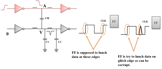
Signal integrity and crosstalk.
 |
| Figure A |
 |
| Figure B |
Clock Tree Algorithms
- H-Tree
- X-Tree
- Method of Mean and Median
- Geometric Matching Algorithms
- Pi Configuration
H-Tree
- Minimize skew by making interconnection to subunits equal in length.

X-tree
- X-tree is similar to H-tree but only difference is the connections are not rectilinear.
Difficulties
- Cross Talk
- Routing is not rectilinear

Method of Mean and Median (MMM)
- Method of mean and median follows the strategy similar to H-tree algorithm, provided the H-tree shape is achieved by proper partitioning of the module.
- It continuously partitions the system into two equal parts (As Fig.) and connects the center of the whole circuit (module) to center of the two sub-circuits (sub-module) and thus produces a non-linear tree.
- Here intersection of wires may be possible.
- Figure shows the exact flow of MMM and the process of partitioning.
- Partition keeps on continues until each division contains only one sub-module.

Geometric Matching Algorithm (GMA)
- Geometric Matching Algorithm (GMA) In fig (A), the physical locations of sub-modules are not symmetric.
- Developing H-tree among these sub-modules is practically not possible.
- At first two sub-modules are grouped together and those trees are named as X-1, X-2, X-3 and X-4 (fig (B)).
- The optimal entry point may not be equidistant from the entry point of X-1 and X-2; buffer insertion can balance the delay because of un-equal net length.
- Then two two-point trees are joined together to form a H like structure. The resultant H-trees are named as X-12 and X-34 (fig (C)).
- As shown in fig (D), the tap points of both the H structure cannot be connected by using rectilinear nets.
- In order to connect the two trees the geometrical position of one H-tree is changed compatible to the other tree’s tap point and the resultant will be as shown in fig (E).

Pi Configuration
- In pi configuration, the total number of buffers inserted along the clock path is multiple of previous level.
- This type of structure uses the same number of buffers and geometrical wires and relies on matching the delay components at each level of the clock.
- The pi structure is clock tree is considered to be balanced. The representation of pi tree is shown in fig.

Clock Tree Optimization Technique
- Buffer and Gate Sizing
- Buffer and Gate Relocation
- Level Adjustment
- Reconfiguration
- Delay insertion
- Dummy Load Insertion
Buffer and Gate Sizing
- Sizes up or down buffers and gates to improve both skew and insertion delay.

Buffer and Gate Relocation
- Physical location of the buffer or gate is moved to reduce skew and insertion delay.

Level Adjustment
- Adjust the level of the clock pins to a higher or lower part of the clock tree hierarchy.

Reconfiguration

Delay Insertion


- Clustering of sequential logic.
- Buffer placement is performed after clustering.
- Longer run times.

Delay Insertion
- Delay is inserted for shortest paths.
- Delay cells can be user defined or can be extracted from by the tool.
- By adding new buffers to the clock path the clock tree hierarchy will change.

Dummy Load Insertion
- Uses load balancing to fine tune the clock skew by increasing the shortest path delay.
- Dummy load cells can be user defined or can be extracted by the tool.

Non Default Routing (NDR)
- Double width.
- Double spacing.
- Shielding - It is the process of shield the clock net by VSS/VDD Nets for reduce cross talk.

Effect Of CTS
- Clock buffer are added.
- Congestion may increase.
- Non-clock cell may have been moved to less ideal location.
Checklist After CTS
- Hold fix are done at CTS? How many buffer are added.
- What skew and latency is achieved after CTS?
- Check QoR report, setup and hold are fixed?
- Only clock buffer or pair of inverter used in the clock tree?
- Timing analysis with OCV and Crosstalk done?
=*=*=*=*=*=*=*=*=*=*=*=*=*=*=*=*=*=*=*=*=*=*=*=*=*=*=*=*=*=*=*=*=*=*=*=*=*=
Disclaimer:-
The content on this blog is contributed/derived from various sources. If you feel that there is any copy right violation please leave a comment and it will be removed. :)
=*=*=*=*=*=*=*=*=*=*=*=*=*=*=*=*=*=*=*=*=*=*=*=*=*=*=*=*=*=*=*=*=*=*=*=*=*=
Disclaimer:-
The content on this blog is contributed/derived from various sources. If you feel that there is any copy right violation please leave a comment and it will be removed. :)
=*=*=*=*=*=*=*=*=*=*=*=*=*=*=*=*=*=*=*=*=*=*=*=*=*=*=*=*=*=*=*=*=*=*=*=*=*=
Comments
Post a Comment